How to Choose a Workholding System for CNC Machining?

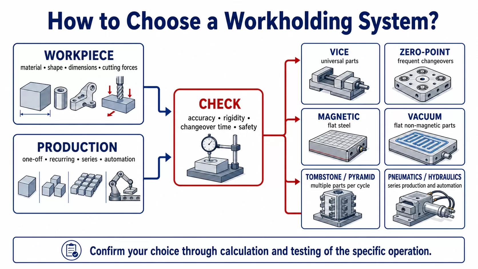
There is no single best workholding system without knowing the specific workpiece and machining operation. For CNC machining, choose a system according to the material, shape and dimensions of the part, the direction of the cutting forces, the required accuracy, the production volume and the time needed for changeovers. A machine vice is often sufficient for flexible one-off production. For repeat orders, a zero-point system with an interchangeable pallet can reduce setup time. Flat steel parts can be held magnetically, while flat non-magnetic parts can be held by vacuum. A tombstone or clamping pyramid can accommodate several parts in one cycle. Automation requires controlled pneumatic or hydraulic actuation, confirmation of the clamped state and safe behaviour in the event of a failure. Always confirm the final choice by calculating the clamping force, testing the specific operation and assessing the risks of the complete workstation.

What Is a Workholding System and Why Does It Affect Manufacturing Accuracy?

This article focuses on holding a workpiece, pallet or fixture on a CNC machine. It does not cover toolholding devices such as collets or shrink-fit holders. This distinction matters because the two areas are often mixed together in search results, although they perform different functions and require different selection criteria.

A workholding system must perform two separate functions. First, it locates the workpiece in a defined position relative to the machine coordinate system. It then holds the workpiece with sufficient force to resist the loads generated by machining. High clamping force cannot compensate for inaccurate location. Conversely, an accurate system that lacks rigidity or adequate support can cause vibration, dimensional variation and poor surface finish.

The entire chain affects the result, from the machine table through the base, pallet and fixture to the jaws or seating surfaces. Every interface adds tolerance and can reduce rigidity. The ZEPO-v workholding system and its related components should therefore be assessed as a complete assembly rather than as isolated catalogue parts.

Which Parameters Affect the Result?

Parameter What needs to be checked Risk of an incorrect choice
Workpiece material and geometry Magnetic properties, flatness, wall thickness and available clamping surfaces Deformation, slippage or inability to use the selected principle
Cutting forces and their direction Type of operation, cutting tool, depth of cut, feed rate and expected load Workpiece movement, vibration or damage to the workpiece and tool
Accuracy and repeatability Required tolerances and the relationship between successive operations Inconsistent dimensions between individual setups
Assembly rigidity Overhang length, supports, number of interfaces and condition of the seating surfaces Chatter, poor surface finish and shorter tool life
Tool access How many sides need to be machined and where jaws or clamps may obstruct the tool More reclamping operations, a longer program and accumulated errors
Changeover speed Time required for mounting, setting and inspecting the first part The machine remains idle even when the machining cycle itself is short
Automation and safety Clamped/released signals, behaviour following loss of energy, air blast and position verification An uncontrolled cycle, collision or unreliable unattended operation

Source for the safety framework: ISO 16090-1:2022 and materials published by the Czech State Labour Inspection Office. See Sources Used.

What Should You Consider When Choosing Workholding?

Start with the workpiece, not the catalogue. The manufacturing engineer needs to know the initial stock, material, dimensions, tolerances, surfaces to be machined and the areas where the part can be held safely. Deformation is likely to be the main risk with a thin-walled aluminium part. Rigidity and the transfer of high loads will be decisive when roughing a steel block. With sheet or plate material, the main limitation may be a small contact area or leakage.

The second input is the production scenario. For a job that runs once a year, a universal solution with a low initial cost may be the most sensible option. If the same part returns every week, repeatable referencing and setup outside the machine become more important. For a long production run, a dedicated fixture that shortens every cycle may be justified even though it is less flexible and must be designed for a specific operation or part.

The third area is economics. Do not compare only the purchase price of the workholding device. Consider setup time, first-part inspection time, the number of reclamping operations, scrap, machine availability, the cost of jaws and fixtures, maintenance and future integration with automation. An inexpensive system can become costly if it increases non-productive time every day.

What Types of Workpiece Holding Systems Are Available and What Are They Used For?

Different principles are often combined. A zero-point system can carry a vice, magnetic plate or special fixture. Pneumatic or hydraulic actuation can operate a vice or another workholding fixture. When making a selection, separate three questions: what locates the workpiece, what holds it and how the clamping process is actuated and monitored.

Machine and Self-Centring Vices

A vice holds the part between jaws and is suitable for rectangular, compact or pre-machined stock. A mechanical vice offers simplicity and flexibility. A self-centring vice locates the part relative to its centre, which is particularly useful for multi-axis machining and when access is needed from several sides. Replaceable soft jaws can be machined to match the geometry of a specific part. 

Zero-Point Systems and Interchangeable Pallets

A zero-point system creates a repeatable reference between the machine table and a pallet, fixture or vice. Its main benefit is not the direct clamping of the workpiece, but the rapid and accurate exchange of the complete workholding assembly. The next part can be prepared outside the machine’s working area.

Magnetic Workholding

A magnetic plate holds a ferromagnetic workpiece across its surface. It provides good access to the top face and reduces obstructing contours. Suitability depends on the material, contact area, part thickness and direction of the applied forces. It is not enough to establish that the material is “steel”. The specific surface condition, geometry and machining process must also be checked. 

Vacuum Workholding

A vacuum plate uses a pressure differential and is suitable for flat, non-magnetic parts such as aluminium, plastic or composite plates. The holding force depends on the effective area and the vacuum level achieved. Porous materials, uneven surfaces, leaks, a decreasing effective area during machining or high lateral forces can all cause problems.

Tombstones, Clamping Pyramids and Multiple-Part Workholding

Tombstones and clamping pyramids increase the usable capacity of the machine’s working area and allow several parts to be held for one cycle. They are particularly useful on horizontal machining centres and in multi-axis machining. The advantage is that more parts can be machined each time the machine is opened. The design must still account for collisions, tool reach, chip evacuation, assembly weight and even load distribution. 

Custom Fixtures

A dedicated or modular fixture is appropriate when standard jaws and plates cannot locate, support or expose the part reliably. With complex castings, forgings and thin-walled parts, correct support can be more important than the clamping force itself. A custom fixture is generally justified only when the time savings and process stability outweigh the cost of design, manufacture, measurement and maintenance.

Pneumatic and Hydraulic Actuation

Pneumatic and hydraulic systems are not locating methods in themselves. They provide and control the clamping force. Pneumatic actuation is generally fast and clean, while hydraulics can deliver higher forces in a compact space. For both systems, it is necessary to define the operating pressure, required force, state following a loss of pressure, position sensing and a safe sequence of steps in the CNC program. 

Solution Typical use Main strength What to check before choosing
Mechanical or self-centring vice One-off and small-batch production of compact parts Versatility and simple changeovers Tool access, deformation, jaw suitability and clamping force
Zero-point system with pallet Repeat orders and frequent changeovers Rapid exchange of the complete assembly and repeatable positioning Interface cleanliness, compatibility, loads and confirmation of the clamped state
Magnetic plate Flat ferromagnetic parts Distributed holding force and unobstructed access to the top face Material, thickness, contact area and lateral forces
Vacuum plate Flat, non-magnetic and thin parts Few mechanical obstructions and reduced local deformation Sealing, effective area, vacuum level and changes in area during machining
Tombstone or pyramid Multiple parts and multi-axis or horizontal machining Better utilisation of the machine’s working area Collisions, reach, chip evacuation, weight and balance of the assembly
Custom fixture Complex parts or parts manufactured repeatedly over a long period Precise adaptation to the process Return on investment, maintenance, measurement and possible future part changes
Pneumatic or hydraulic actuation Series and automated production Controlled, repeatable cycle Safe behaviour following a failure, sensors, pressure, maintenance and integration

Source: the technical principles are a synthesis of general engineering practice, ISO 16090-1:2022 and v-tech product categories. Suitability for a specific application must be confirmed by calculation and testing of the relevant operation.

Decision guide for choosing a CNC workholding system by workpiece and production type

When Should You Choose a Zero-Point System?

A zero-point system makes the most sense where fixtures, vices or pallets are changed frequently and repeat setting currently accounts for a significant share of non-productive time. Typical scenarios include repeat orders, small batches of multiple products, setup outside the machine or a workstation that will eventually be served by a robot or pallet loader.

First measure the current process. Separate machining time from the time during which the machine is stopped for table cleaning, workholding installation, alignment, measurement and first-part inspection. A zero-point system provides an economic benefit when the time saved and the more stable return to the reference position offset the investment in bases, pallets, pins, fixtures and maintenance.

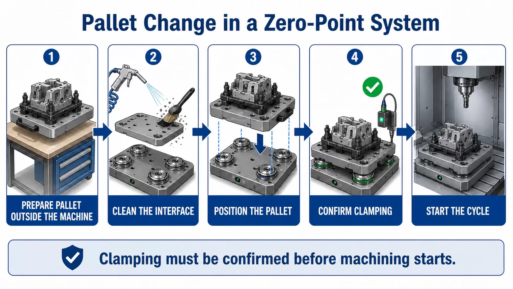
During the technical design, check the permissible forces and moments, the number and position of clamping points, protection against unintended release, cleanliness of the seating surfaces and the method used to confirm the clamped state. In an automatic cycle, the control system must know unambiguously that the pallet is correctly seated and secured before machining starts.

Five steps for changing a pallet in a zero-point workholding system

Which Standards, Regulations and Inspections Apply to Workholding?

No standard or law will select a specific vice for the manufacturing engineer. They do, however, define the framework within which the machine, workholding system and operator must be safe. When designing a new workstation or making a substantial modification, assess the workholding device as part of the complete system and determine whether the change affects the machine’s conformity assessment.

  • ISO 16090-1:2022 covers the safety of machining centres, milling machines and transfer machines. It also covers power-operated workpiece holding and workpiece handling mechanisms. The design must address significant hazards during setting, operation, cleaning, maintenance and reasonably foreseeable misuse.
  • Czech Government Regulation No. 176/2008 Coll. sets out the technical requirements for machinery in the Czech Republic and, according to the Czech Collection of Laws, remains in force until 20 January 2027.
  • Regulation (EU) 2023/1230 on machinery will replace the existing European directive and will apply from 20 January 2027. Projects placed on the market around this date must be checked against the transitional provisions and the current harmonised standards.
  • Czech Government Regulation No. 378/2001 Coll. lays down requirements for the safe operation and use of machinery and technical equipment. Operators must pay particular attention to the accompanying and operating documentation, inspections, maintenance and local rules for safe use.
  • The Czech State Labour Inspection Office and Regional Labour Inspectorates supervise occupational safety and the operation of equipment at workplaces. In its guidance for metalworking machine tools, the State Labour Inspection Office requires the function of the workholding device to be checked before work begins and permits only items for which the device is intended to be clamped.
  • The Czech Trade Inspection Authority supervises the supply of designated products to the market under Czech conformity assessment legislation unless another authority is specified by a special law. Occupational safety during operation and market surveillance are therefore not the same thing.

Czech and ISO standards are revised periodically. Before manufacturing or substantially modifying a workstation, confirm the current edition, its applicability to the particular machine and its harmonisation status where relevant. Documentation must be supported by a real risk assessment, instructions, testing and maintenance rules.

How Should You Choose a Solution for Your Type of Production?

Production situation Likely starting point Key question before making a decision
One-off production and prototypes Universal mechanical or self-centring vice Can parts be changed without expensive dedicated jaws?
Recurring small batches Zero-point system, interchangeable pallet or modular fixture How much time is currently spent on repeat setting and first-part inspection?
Long production run of the same part Custom fixture with pneumatic or hydraulic actuation Will the investment be recovered through a shorter cycle and a more stable process?
Flat steel parts Magnetic plate Are the area and thickness sufficient for the loads generated by the operation?
Flat non-magnetic parts Vacuum plate Will an effective sealed area remain throughout the machining operation?
Multiple parts in one cycle Tombstone, pyramid or multi-part fixture Does the working area provide safe access without collisions or chip accumulation?
Robotic loading Controlled pneumatic or hydraulic clamping, pallets and a zero-point system Can every state be detected unambiguously and can failures be handled safely?

Source: v-tech decision framework. A specific design requires technical data for the workpiece, machine and operation.

Summary

How Do You Choose a Workholding System in 10 Steps?

  1. Describe the workpiece. Provide the material, initial geometry, dimensions, weight and a 3D model or drawing.
  2. Define the clamping and machining surfaces. Clarify where the part can be held and where the tool needs access.
  3. List the operations and forces. Distinguish between roughing, finishing and drilling, and identify the direction of the main load.
  4. Set the accuracy and repeatability requirements. State the tolerances and whether the part will be set up again between operations.
  5. Consider deformation and rigidity. For thin parts, do not focus only on maximum force. Ensure correct support and pressure distribution.
  6. Assess production volume and changeover frequency. Include the batch size, number of variants and frequency of repeat orders.
  7. Measure non-productive time. Record workholding installation, alignment, cleaning, part changes and first-part inspection.
  8. Check the machine and its working area. Verify the table interface, axis travel, weight, collision envelope, utilities and control system.
  9. Define automation and safety requirements. Specify signals, behaviour following loss of energy, cycle interlocks, maintenance and inspections.
  10. Validate the design through testing. Confirm the clamping force calculation, simulation, trial machining, measurement and documentation.

The right CNC workholding system is selected from a measurable process, not from a product name. If you are planning a new workholding setup, dealing with repeated setup work or preparing a workstation for automation, send your technical information to v-tech for a non-binding consultation. The design can be assessed according to the workpiece, machine, production cycle and required level of automation.
 

Frequently Asked Questions

  • How Can You Reduce CNC Machine Setup Time?
    First measure where the machine is idle. If time is being lost on installation, alignment and repeatedly finding the reference position, a zero-point system and preparing the pallet outside the machine can help. If the problem lies with the jaws, standardising vices, stops and interchangeable jaws may be sufficient. Any reduction in setup time must preserve checks for cleanliness, correct seating and safe clamping.
  • What Is a Zero Point in CNC Workholding?

    A zero point is a defined interface that allows a pallet, fixture or vice to be positioned repeatedly at the same reference location. The workpiece may be held on the pallet by another device. The main benefit of a zero-point system is the rapid exchange of the complete assembly and a reduction in repeated setting work.

  • What Is the Difference Between a Zero-Point System and a Vice?
    A vice clamps the workpiece directly between its jaws. A zero-point system normally locates and secures a pallet, fixture or the vice itself relative to the machine. The two components are therefore often used together.
  • When Should Pneumatic or Hydraulic Clamping Be Used?
    Use pneumatic or hydraulic clamping for frequently repeated cycles, when controlled force is required or when integrating the process with automation. Pneumatics are generally fast and clean, while hydraulics provide a higher force in a compact space. State sensors, pressure, maintenance, safe behaviour following a failure and machine-start interlocks must always be addressed.
  • How Can You Verify That the Clamping Force Is Sufficient?
    The calculation must account for the magnitude and direction of the cutting forces, friction, support locations, contact geometry and an appropriate safety margin. It should be supplemented by checking the manufacturer’s permissible loads, simulation and measured trial machining. The rated force of a workholding device alone is not sufficient without knowing the complete assembly.

Leave us a message and we will get back to you as soon as possible.

  • Fields marked with an asterisk (*) are required.

Sources Used

  1. ISO. ISO 16090-1:2022, Machine tools safety, Machining centres, milling machines, transfer machines, Part 1: Safety requirements. https://www.iso.org/standard/81558.html
  2. Czech Collection of Laws. Czech Government Regulation No. 378/2001 Coll., laying down detailed requirements for the safe operation and use of machinery, technical equipment, devices and tools. https://e-sbirka.gov.cz/sb/2001/378
  3. Czech Collection of Laws. Czech Government Regulation No. 176/2008 Coll., on technical requirements for machinery. https://e-sbirka.gov.cz/sb/2008/176
  4. EUR-Lex. Regulation (EU) 2023/1230 of the European Parliament and of the Council on machinery. https://eur-lex.europa.eu/legal-content/EN/TXT/?uri=CELEX:32023R1230
  5. Czech State Labour Inspection Office. Occupational safety principles for metalworking machine tools. https://www.suip.cz/documents/20142/43837/desatero_obrabeci_stroje.pdf/272edf70-0af7-18ed-9d3f-04bba078f79a
  6. Czech Office for Standards, Metrology and Testing. Machinery. https://unmz.gov.cz/statni-zkusebnictvi/stanovene-vyrobky/strojni-zarizeni/

Author Box

Author: v-tech s.r.o.
Technical reviewer: Michal Vašát
Updated: August 2026
v-tech s.r.o. designs and manufactures workholding systems, components for CNC production and automation solutions. This article is based on the company’s technical documentation, product information and the current safety sources listed above.

This website uses cookies

This website is using cookies to provide services, personalize ads, and monitor traffic. By continuing to use this site you are agreeing with usage of cookies. More information.